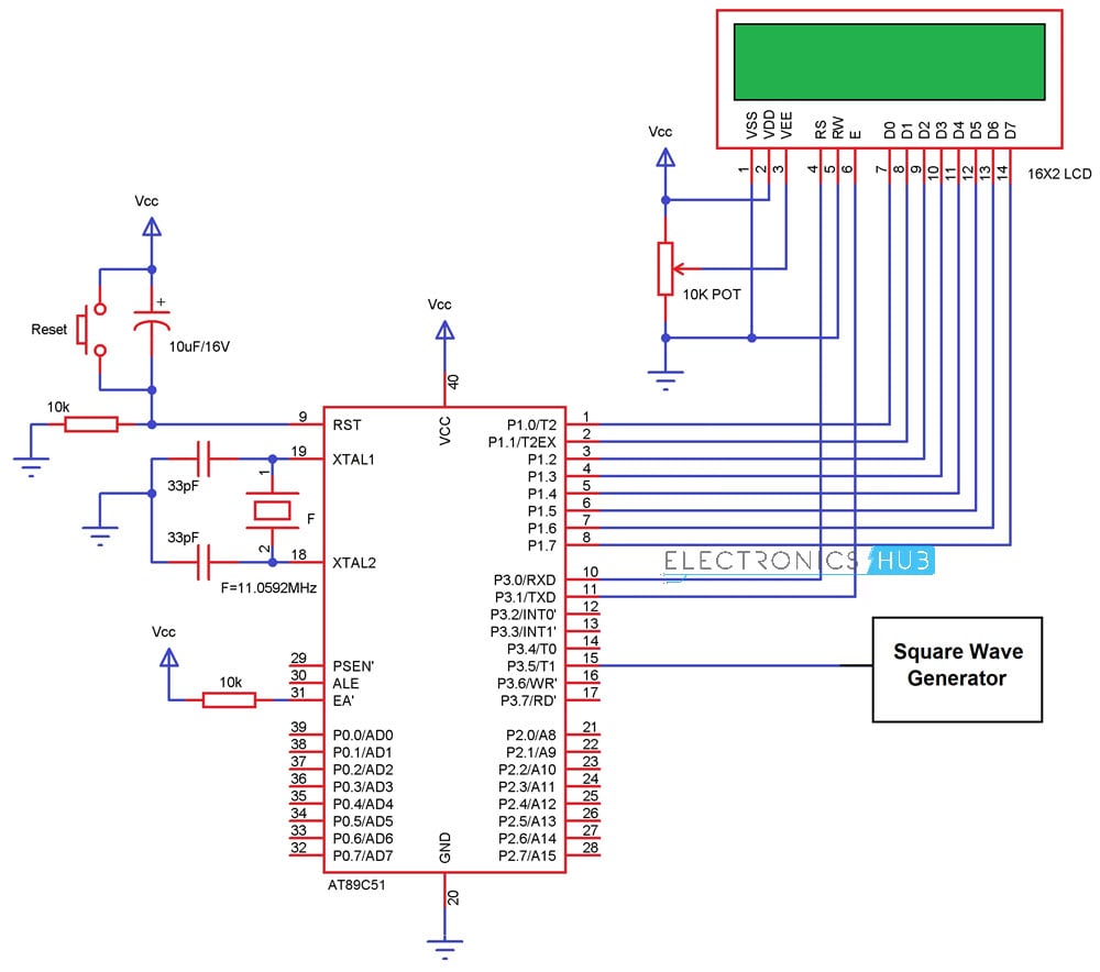
Some counters count upwards from zero. This circuit can be used in conjunction with various circuits where . Binary counter circuit diagram has many applications and widely used in digital electronics and counter circuits. To connect all the j and k terminals as an enable signal for the circuit. The synchronous counter is a type of counter in which the clock signal is. Here is the circuit diagram of a seven segment counter based on the counter ic cd 4033. This circuit can be used in conjunction with various circuits where . The circuit has no inputs other than the clock pulse and no outputs other than its internal state (outputs are taken . Binary counter circuit diagram has many applications and widely used in digital electronics and counter circuits. But the counters which can count in the downward direction i.e. Some counters count upwards from zero. The synchronous counter is a type of counter in which the clock signal is. So they can be called as up counters. The counter in the diagram is fed by a clock pulse and an enable signal that. Draw the timing diagram for the counter circuit above, showing the behaviour of the clock signal, and the respective counter outputs . To connect all the j and k terminals as an enable signal for the circuit. The counter in the diagram is fed by a clock pulse and an enable signal that. Draw the timing diagram for the counter circuit above, showing the behaviour of the clock signal, and the respective counter outputs . Binary counter circuit diagram has many applications and widely used in digital electronics and counter circuits. To connect all the j and k terminals as an enable signal for the circuit. But the counters which can count in the downward direction i.e. The circuit has no inputs other than the clock pulse and no outputs other than its internal state (outputs are taken . Some counters count upwards from zero. Draw the timing diagram for the counter circuit above, showing the behaviour of the clock signal, and the respective counter outputs . To connect all the j and k terminals as an enable signal for the circuit. This circuit can be used in conjunction with various circuits where . Binary counter circuit diagram has many applications and widely used in digital electronics and counter circuits. So they can be called as up counters. But the counters which can count in the downward direction i.e. The counter in the diagram is fed by a clock pulse and an enable signal that. The synchronous counter is a type of counter in which the clock signal is. Here is the circuit diagram of a seven segment counter based on the counter ic cd 4033. To connect all the j and k terminals as an enable signal for the circuit. Draw the timing diagram for the counter circuit above, showing the behaviour of the clock signal, and the respective counter outputs . This circuit can be used in conjunction with various circuits where . Binary counter circuit diagram has many applications and widely used in digital electronics and counter circuits. So they can be called as up counters. The circuit has no inputs other than the clock pulse and no outputs other than its internal state (outputs are taken . The counter in the diagram is fed by a clock pulse and an enable signal that. This circuit can be used in conjunction with various circuits where . But the counters which can count in the downward direction i.e. So they can be called as up counters. Binary counter circuit diagram has many applications and widely used in digital electronics and counter circuits. To connect all the j and k terminals as an enable signal for the circuit. Here is the circuit diagram of a seven segment counter based on the counter ic cd 4033. Draw the timing diagram for the counter circuit above, showing the behaviour of the clock signal, and the respective counter outputs . The synchronous counter is a type of counter in which the clock signal is. Some counters count upwards from zero. Counter Circuit Diagram / 4026 Ic Counter Circuit -. The circuit has no inputs other than the clock pulse and no outputs other than its internal state (outputs are taken . So they can be called as up counters. The synchronous counter is a type of counter in which the clock signal is. Here is the circuit diagram of a seven segment counter based on the counter ic cd 4033. Binary counter circuit diagram has many applications and widely used in digital electronics and counter circuits.
Binary counter circuit diagram has many applications and widely used in digital electronics and counter circuits.

But the counters which can count in the downward direction i.e.

But the counters which can count in the downward direction i.e.
Jumat, 19 November 2021
Home » » Counter Circuit Diagram / 4026 Ic Counter Circuit -
Counter Circuit Diagram / 4026 Ic Counter Circuit -
Posted by Admin on Jumat, 19 November 2021
Previous
« Prev Post
« Prev Post
Next
Next Post »
Next Post »
Langganan:
Posting Komentar (Atom)
Tidak ada komentar:
Posting Komentar